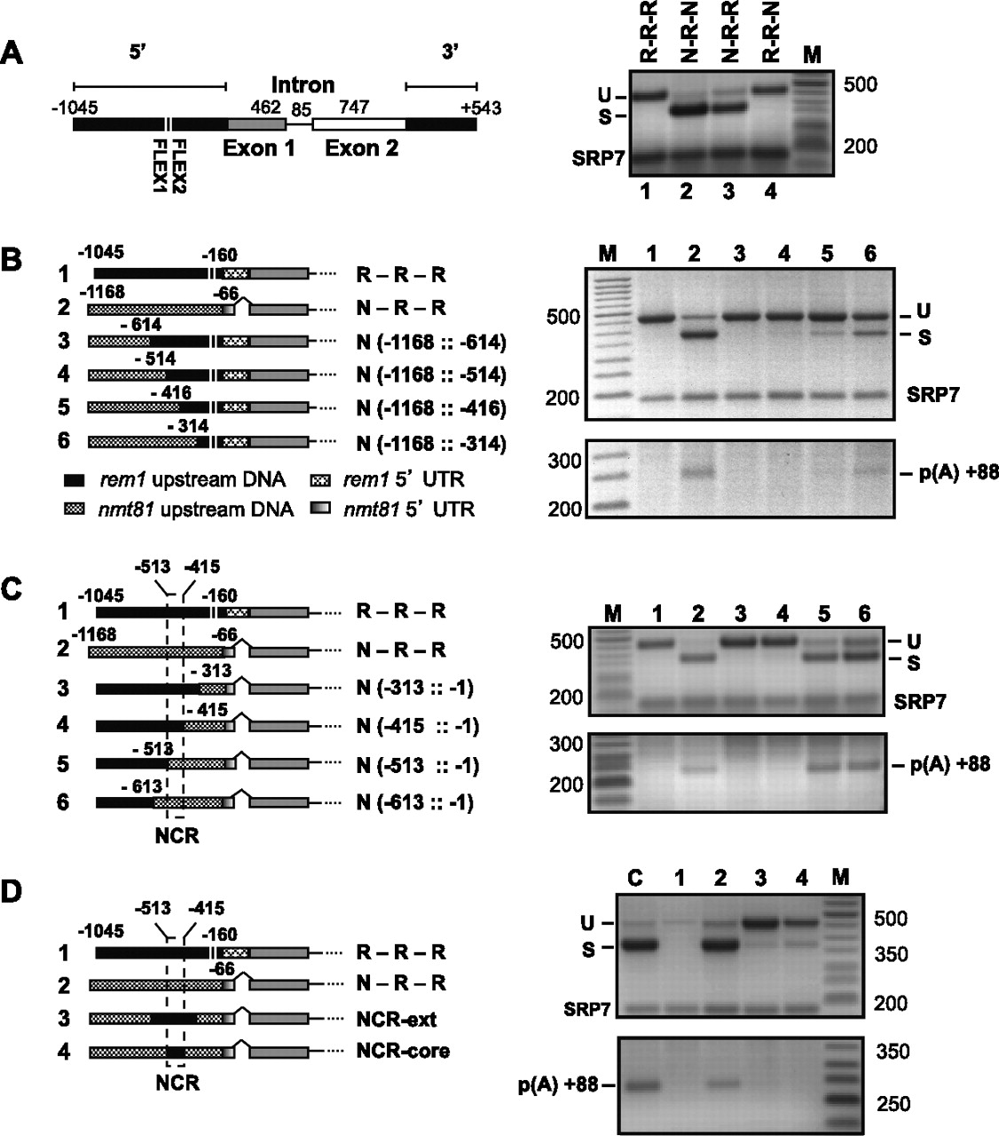
Mapping of the region that negatively controls rem1 RNA processing. (A) The element that prevents rem1 splicing in proliferating cells is located upstream of the coding region. (Left) Diagram of the wild-type insert, with noncoding DNA represented by black rectangles, the coding portions of exons 1 and 2 by gray and white rectangles, respectively, the intron by a horizontal line, and the FLEX boxes centered at −178 and −219 relative to the ATG by vertical white lines. Chimeric genes were created by replacing rem1 sequences surrounding the ORF with the corresponding segments of the nmt81 (no message on thiamine) vector, a commonly used expression system in fission yeast (see Materials and Methods). (Right) RT-PCR splicing assays on RNA isolated from cells transformed with the indicated constructs. Chimeras are labeled with a three-letter code indicating the source of the 5′, internal, and 3′ segments; (R) rem1, (N) nmt81: lane 1, wild type (R-R-R); lane 2, substitution of both 5′ and 3′ DNA (N-R-N); lane 3, substitution of 5′ DNA only (N-R-R); lane 4, substitution of 3′ DNA only (R-R-N). To eliminate endogenous signals, analyses were carried out in the rem1 gene deletion strain JLP1014 (Averbeck et al. 2005). (B,C) Splicing (top) and polyadenylation (bottom) assays on the constructs diagrammed at the left, in which increasing amounts of rem1 DNA are replaced with nmt81 sequences. The two FLEX boxes identified in a previous study (Moldon et al. 2008) are indicated by white lines. As the rem1 5′ UTR is longer than the nmt81 5′ UTR (see Materials and Methods), carets (^) are inserted into the diagrams of constructs carrying the latter to preserve ORF alignment. (D) Splicing (top) and polyadenylation (bottom) assays on chimeras in which the 5′ DNA is derived from nmt81, except for the 98-nt NCR (core) or an additional 100 nt upstream and downstream (ext).